...
5 Frequency
Attenuation is a loss of intensity in an energy beam as it passes through a substance or object or the energy loss of signal transmission through a given medium. Coefficient is a quantitative measure of either an effect or a property. It is the ratio by which a change in one property will change another property. The attenuation coefficient is thus a ratio comparing the loss of intensity to the distance that the energy beam passes through the material. The units used to express the intensity will depend on the precise energy beam.
The attenuation coefficient is also used in ultrasound. When ultrasound waves propagate in a medium, energy is removed from the ultrasound waves by two main processes, absorption and scattering.The mechanism that removes energy from the ultrasound waves is called “attenuation”. Ultrasound is absorbed by the medium if part of the wave energy is converted into other forms of energy, such as heat. The absorption is frequency dependence. When ultrasound waves propagate, they not only become smaller in amplitude but they also change shape. Absorption in the body has a major effect on the penetration depth. It would limit the detectable penetration of the ultrasound waves in the body or the maximum depth at which tissues can be imaged. The attenuation of ultrasound in a material could be described by the attenuation coefficient in the units of decibels per centimetre per megahertz (dB/cm/MHz).
Attenuation always serves as a measurement parameter that leads to the formation of theories to explain physical or chemical phenomenon, which decreases the ultrasonic intensity. Attenuation is generally proportional to the square of sound frequency. Quoted values of attenuation are often given for a single frequency, or an attenuation value averaged over many frequencies may be given. The attenuation coefficient (α) can be used to determine total attenuation in dB in the medium using the following formula:

α: attenuation coefficient ℓ: medium length
ƒ: frequency of the incident ultrasound beam
The attenuation coefficients of common biological materials at a frequency of 1 MHz are listed below:
| Material | a (dB / (MHz ; cm)) |
|---|
| Air | 1.64 (20°C) |
| Blood | 0.2 |
| Bone, cortical | 6.9 |
| Bone, trabecular | 9.94 |
| Brain | 0.6 |
| Breast | 0.75 |
| Cardiac | 0.52 |
| Connective tissue | 1.57 |
| Dentin | 80 |
| Enamel | 120 |
| Fat | 0.48 |
| Liver | 0.5 |
| Marrow | 0.5 |
| Muscle | 1.09 |
| Tendon | 4.7 |
| Soft tissue (average) | 0.54 |
| Water | 0.0022 |
Figure 1. Diffuse reflection. Copied from [1]
References
- Culjat, Martin O.; Goldenberg, David; Tewari, Priyamvada; Singh, Rahul S. (2010). "A Review of Tissue Substitutes for Ultrasound Imaging". Ultrasound in Medicine & Biology 36 (6): 861–873.
- Tole, Nimrod M. (2005). Basic physics of ultrasonographic imaging.
Chapter 3: http://www.isradiology.org/isr/docs_books/basic/Chapter3.pdf - Michael L. Oelzea; William D. O’Brien, Jr. (2002). Frequency-dependent attenuation-compensation functions for ultrasonic signals backscattered from random media.
6 Other Variable Dependencies
In fiber optic, attenuation is the loss of signal energy or intensity when signal is transmitted in long distance. There are many factors that cause attenuation. In general, attenuation is caused by the medium components such as, cables, connectors. Below are factors that degrade the signal strength in the fiber.
The first phenomenon is optical absorption. When light travel through the optical fiber, photons can be observed by the material structure which result in the higher energy state of the material. Because of photon absorption, light loses its intensity and hence signal is degraded. The travel of light can be described in the following formula:
n * = n (y) + ik (y)
n*: complex refractive index
n(ω): real portion of the refractive index
n (h): extinction coefficient
So, the material structure has a effect on the signal strength through optical absorption.
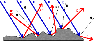
The next factor is light scattering. If the surface of the material is rough and uneven, propagation of light in the fiber can be reflected in random direction. This kind of reflection is also called as diffuse reflection.
Figure 1. Diffuse reflection. Copied from [1]
As we can see, the blue lights hit the surface of the core. If the surface is rough, the reflected red lights will go in random directions following the low of reflection. This results in the loss of the light power.
Next one is connection loss. It is important to align two fibers correctly because it will minimize the lateral offset of the core, tilt, angular mismatch... Fiber misalignment can have large impact on the signal loss because the light is not reflected correctly.
Figure 2. Two spliced fibers. Copied from [2]
The above image shows the misalignment between two fibers that affect the fiber coupling efficiency. Moreover, air between fiber connections may exist and has impact on the medium. Therefor, air should be minimized as much as possible to produce an optimal medium for propagation of light.
References
References
1. http://www.ece.umd.edu/~davis/optfib.html
2. Azadeh, M. (2009). Fiber optics engineering.
Azadeh, M. (2009). Fiber optics engineering.
- Introduction to optical fibers, dB, Attenuation and measurement:
http://www.cisco.com/c/en/us/support/docs/optical/synchronous-digital-hierarchy-sdh/29000-db-29000.html - Optical Power loss measurement in db- how to measure it fast and correct
http://www.ad-net.com.tw/?id=474
- Culjat, Martin O.; Goldenberg, David; Tewari, Priyamvada; Singh, Rahul S. (2010). "A Review of Tissue Substitutes for Ultrasound Imaging". Ultrasound in Medicine & Biology 36 (6): 861–873.
- Tole, Nimrod M. (2005). Basic physics of ultrasonographic imaging.
Chapter 3: http://www.isradiology.org/isr/docs_books/basic/Chapter3.pdf - Michael L. Oelzea; William D. O’Brien, Jr. (2002). Frequency-dependent attenuation-compensation functions for ultrasonic signals backscattered from random media.
- Reflection and the Ray Model of Light - Lesson 1 - Reflection and its Importance
http://www.physicsclassroom.com/class/refln/Lesson-1/Specular-vs-Diffuse-Reflection - B.G. Potter. Module 3 - Attenuation in optical fibers
http://opti500.cian-erc.org/opti500/pdf/sm/Module3%20Optical%20Attenuation.pdf

