Introduction
Infrared radiation is an electromagnetic wave with wavelength of 700nm to 1 mm. It is emitted by objects with temperature above 0 kelvin. Furthermore intensity and wavelength of infrared radiation depends on the temperature of the object.
The infrared sensors are the sensors that detect/measure infrared radiation or change in the radiation from outer source source or inbuilt source.
There are two types of infrared sensor based on its function:
- Thermal Infrared sensor:
- Quantum infrared sensor
The working method of most infrared sensor is as follows.
Detection System
The detector performance is based on to following parameters:
Photosensitivity:
It is the output voltage per watt of incident energy in absence of noise.
R=S/AP
R= photosensitivity(V/W)
S= output voltage(V)
A= Active area/Exposed area(cm2)
P= Incident Energy(W/cm2)
A simple circuit for obtaining output voltage(signal) consists of a current source, photodetector(dark resistance), a resistor and a voltage output.
Figure 1 Example of basic circuit for signal output/1/
In the circuit when radiation strikes the resistor Rd then its resistance changes consequently changing the voltage output Vo.
D*: It is the photosensitivity per unit active area of the detector. Therefore, higher D* means better performance.
Noise Equivalent Point(NEP): Noise is caused by the background radiation and it affects the signal output. NEP is the amount of incident radiation when the signal to noise ratio is 1.
Physics behind infrared sensors:
Plank’s radiation law-
The body which has temperature greater than 0 K radiates. Infrared cannot be seen through normal eyes. It describes the electromagnetic radiation emitted by black body in thermal equilibrium. Plank law can be expressed
h= 6.625×10⁻²⁷ erg-sec (plank Constant)
k=1.38×10⁻¹⁶ erg/K (Boltzmann Constant)
c= 3×1010 cm/sec (Speed of light)
Stefan-Boltzmann Law
The thermal energy radiated by a blackbody radiator per second per unit area is proportional to the fourth power of the absolute temperature and is given by
Stefan-Boltzmann law
Wien’s Displacement law- The radiated energy is different in different temperature it increases with increase in temperature.
For the blackbody radiation the law is
For other bodies beside blackbodies the relation is given as emissivity (E)
Types of Infra-Red Sensors
ACTIVE INFRARED SENSORS
Active infrared sensors are the types of infrared sensor that emit infrared radiation which is later received by the receiver. The IR is emitted by a IR Light Emitting Diode (LED) and received by photodiode, phototransistor or photoelectric cells. During the process of detection, the radiation is altered, between process of emission and receiving, by object of interest. The alteration of radiation causes change in received radiation in the receiver. This property is used to generate desired output with help of associated electronic circuit.
There are two types of Active infrared sensors
Break beam sensors
These types of Active IR sensor have emitter and receiver placed in such a way that the IR emitted by the emitter falls directly in to the receiver. During the operation, IR beam is emitted continuously towards the receiver. The flow of IR can be interrupted by placing an object between the emitter and receiver. If the IR is transmitted but altered then receiver generates output based on the change in radiation. Similarly if the radiation is completely blocked the receiver can detect it and provide the desired output. For example: let’s consider a Break beam sensor and a conveyer belt as shown in figure. When an opaque object interrupts the IR flow the receiver doesn’t receive any signal thus the conveyer belt stops.
Figure 1 Break Beam Sensor Example
Furthermore advanced use of these types of sensors can be to acquire different shape and surface profile of objects.
Reflectance sensors
These types of sensors use reflective property of IR. The emitter emits an IR beam which is reflected by the object. The reflected IR is the detected by the receiver. The object causes change in the property of the reflected IR or the amount of IR received by the receiver varies. The degree of change is dependent on the reflectance of the object. Thus detecting the change in amount of received IR helps in figuring out the properties of object such as surface geography and reflectance.
Figure 2 Reflectance sensor
Passive Infrared Sensor
Passive infrared sensors detect the infrared radiations from outer source.When an object is in a field of view of a sensor it provides a reading based on a thermal input.It dose not generate any infrared.
Pyroelectric infrared sensor(PIR)
Working Principle
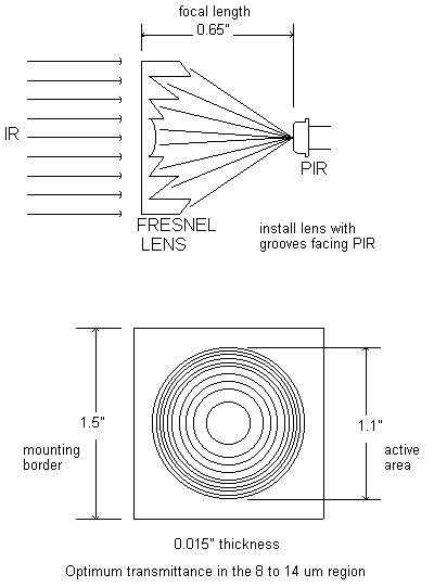
The infrared sensor has its detecting area. Multizonal Fresnel lens array is associated covers the pyroelectric transducer. This lens is Plano convex lens that are designed to collect the infrared radiation from the different spatial zones.Fresnel lens are made up of material that can transmit infrared range of 8µM to 14µm. This lens dose not view the space in continuous fashion, the detection pattern of sensor is fan shaped .It views as a discrete beams or cones.[4]
Figure 4: Fresnel Lens
Figure 5 :detection pattern of the sensor
The gap between the cones increases with the distance and it is inversely proportional to the sensitivity of the sensor.
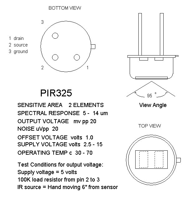
The PIR sensors have two pins 1 and 2 they are activated when a radiation source passes is in the field of view. Pins are wired as opposite input. Pin 1 activates when radiation source come across the Pin 1 which is positive zone and the sensor values goes up, when the radiation source continues towards Pin 2 which is negative zone the value drops and the value comes to 0, this activity causes the net positive effect on the sensor value.[6]
Figure 6 :principle of PIR sensor
The radiation strikes pryoelectric films that are made of lithium tantalite. It is dielectric (insulator) in nature so its surface area charges when it is strike by radiated infrared. It has electrodes which gather the charge. The produced charge is measured with FET (Field effective transistor) device that is inbuilt in sensor. Among 3 pins in the FET pin 3 is grounded about 100k and pin 2 is feed into a stage amplifier having signal condition circuits.
The amplifier avoids the high frequency noises above 10Hz. The signal produced is in the range of 1mVpp that is a small voltage around a DC signal. The power source of 3 to 15 volt is required for the FET supplied through Pin 1.Externtal resistor is connected to pin 3 and pin 2 which converts the FET current to voltage. Pin 2 of a FET is followed by Amplifier and comparator. To improve the accuracy of sensor dc offset (dc offset is an undesirable character, it causes waveform not to be 0) is eliminated by PIR incorporation of ac-coupled amplifiers. Comparator is an extremely sensitive device comparing the voltages or currents and gives outputs a digital signal which is larger.[2][3]
Figure 7:Field effective Transistor
Figure 8:Application block diagram
PIR have four op-amps (operational amplifiers) two for amplification stage and one for voltage follower and one as a comparator. The signal from the FET is amplified and the Amplifier 1 provides gain (gain is a unit less measure of the ability of an amplifier to increase the amplitude of a signal from the input to the output) and the signal is buffered in a signal adaptor and it is passed to the Amplifier 2 to provide another gain. Ratio gain in staged amplifiers is multiplied. Then the signal is fed into the A/D convertor (Analog to Digital converter) it converts the analog voltage signal into binary signals and the binary signal encodes the analog input as a result the output is in digital number.[7]
Analog-digital converter uses that comparator compares the signal value with the threshold value. The threshold value of the PIR sensor is kept low to capture weak motions if the signal value is between the two threshold values that mean there is no motion and the reading is 0 V. If signal value is higher than the threshold value then the sensor has detected a motion, and the indicator is activated to identify the detection of motion.[2],[7]
Drawbacks
- The result of the PIR sensor is affected by various external factors such as temperature change, sunlight to avoid such factors the sensor has two sensing elements that are connected to voltage bucking configuration.
- The radiation detectors are in horizontal plan which makes sensor to detect object possible in only in horizontal position.
Application
- SECURITY
- Lighting appliances
- Household or other appliances
Thermal infrared sensors
Thermal infrared sensors which are also called radiation detectors undergo a change in temperature due to absorption of infrared radiation and convert this temperature change into an electric output signal. Their working principle varies compared to semiconductor based photon or quantum sensors which works on principle that due to different photoelectric effects the photons of the radiation generate charge carriers. For the sensors which work on photoelectric effects, to detect the low-energy infrared radiation, sensors have to be cooled below ambient temperature. In contrary to this, thermal infrared sensors can be operated at ambient temperature. The radiation noise that limits temperature resolution in thermal sensors has a √T dependence meaning that the cooling doesn't consequently improve detection rate. Hence they are more suitable for small, light and portable applications.
Working Principles:
Thermal radiation sensors convert radiant flux ᶲs into an electric signal (Voltage VS or Current IS). Figure represents the measuring chain of radiation sensors. Even though there are various operating principles the basic structure of all the thermal IR are identical. The incident IR radiant flux is absorbed by a thermally isolated detector element (pixel) and it is converted into heat. The temperature of the pixel is directly proportional to the power of the absorbed IR radiation. This makes the responsivity of thermal sensors independent of wavelength. However, in many scenarios there is a wavelength dependence of responsivity due to absorption characteristics of the pixel. If required IR radiation can be temporarily modulated with a chopper. The conversion of the pixel temperature into an electrical signal depends on the sensor type.
Figure: Measuring chain for determining infrared sensors.
IR sensors consist of a thin well isolated chip usually called as detector. The temperature of the detector depends on the absorbed radiant flux ᶲA and the radiant flux ᶲS emitted by the detector element. The figure below illustrates the radiation exchange at detector element, object and detector surroundings. The possible heat flow between detector element, object and detector surroundings due to the thermal conduction is neglected.
Figure:Radiation exchange at detector element.
References
- Hamamtsu Infrared detectors/technical information
- http://www.thesis.bilkent.edu.tr/0003853.pdf
- http://www.glolab.com/pirparts/infrared.html
- http://www.sbf1.sbfisica.org.br/procs/2006/pdfs%20optics/Interferometry,%20Holography%20and%20Applied%20Optics/604%20-2.pdf
- http://www.st.com/st-web-ui/static/active/en/resource/technical/document/application_note/DM00096551.pdf
- http://www.hitechnic.com/cgi-bin/commerce.cgi?preadd=action&key=NIS1070
- http://www.cypress.com/?docID=3317


